LED Dimmer – led light controlling machine
LED Dimmer – led light controlling machine
Using Raspberry Pi, Android phone and IKEA LED lights !
Introduction
The project was developed at a time of great despair in my own electronics skills. Let’s start from the beginning. When you buy a tv set, you place it in a very noble place, turn it on, turn it off and don’t watch it – what for should You watch it :). Nonetheless as a electronic and software developer you can’t stand that this kind of device is left without any additional perks made by yourself. As everyone knows, tv is best watched when there is no much visual difference between background and foreground of the tv picture. The eye is much more strained, when it has to look on dark and bright areas continouosly. Sometime ago one of tv set manufacturer (as I remember Philips) has made a tv with an ambient color lamps placed on the back of the tv set. The color was changing, accordingly to the foreground dominant color eg. when you watch soccer game, you end with a green background color. It was fun to look at, and quite pleasant to use. Now, just when the tv set was placed in my room, i was thinking how can I do it by ourself. The end result is shown on the video below.
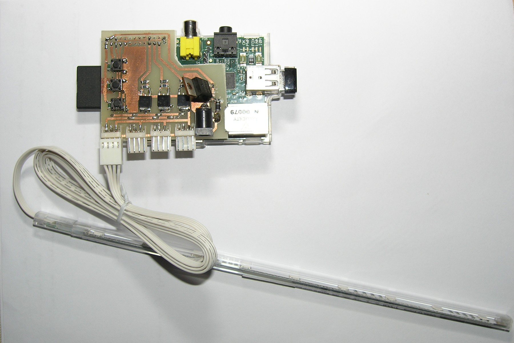
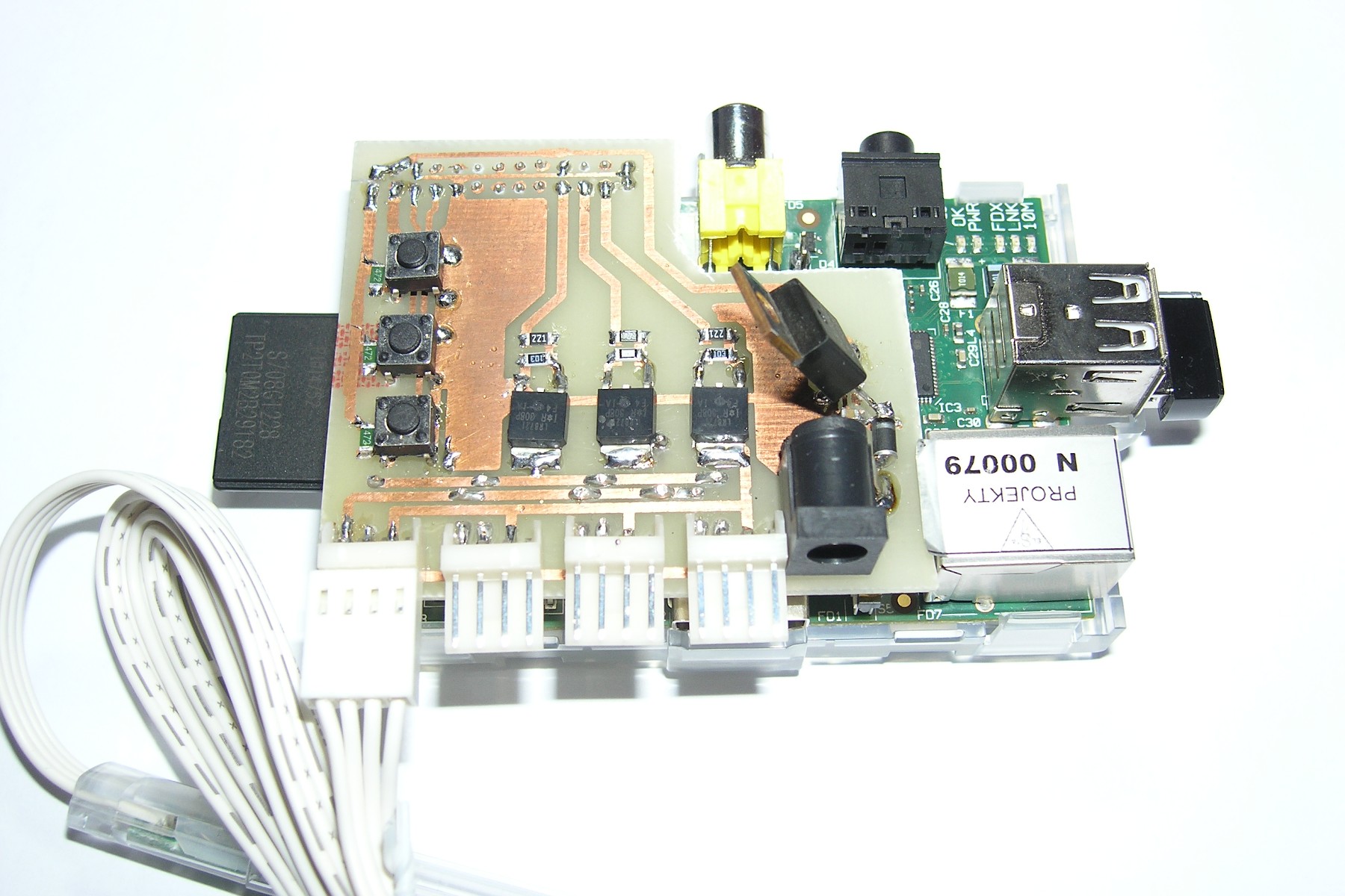
Device ready to go !
But first of all, let’s start from the beginning. The technology details, the needed equipment and further more into details 🙂
Functional description
As it was stated before, our goal is to build our own LED lights controller, which connected to the LED lights strips and put back on the tv set will provide additional visualization for tv display. Of course, when something struck you in the head as an ingenious idea, the reality is that someone already and most probably a long time ago, discovers it and right now it’s being produced on the massive scale 😉 It is known, that this solution is popular and can be bought without much problem. Each such product is a simple power supply, manual controller and LED strips. And there is something which will be different in our case. As a lazy person, I found it quite cumbersome to walk to the tv set in order to change the mode or turn it on/off. In our design, we will have remote control and even with our phone (well maybe most of us will have at least one android device in the house).
LED Lights
As I already said, many devices are already available and I myself has bought one of these. This was a simple step to take a look at the device build, what is realy needed for this kind of device and it provide me a device already in place, when I will keep trying to build it myself 🙂 The device is IKEA DIODER set which consist of power supply, controller + splitter and set of LED strips. Everything is illustrated in the figure below.
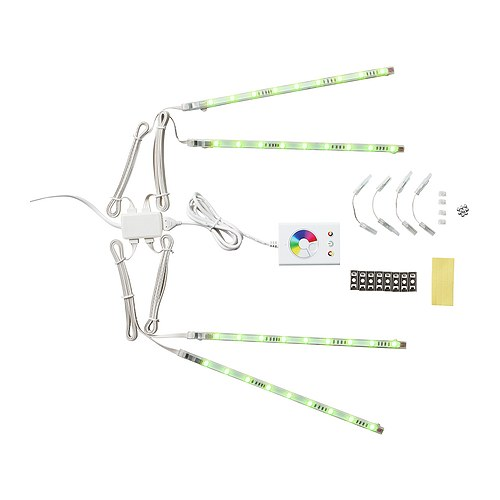
Fig. IKEA Dioder LED Lights – (c) IKEA
The device works pretty good, without any problems and it is doing what is meant to. It has several modes: static color defined in what you choose on the color dial. Next mode is a smooth transition through the whole color scale, the third mode is a color switching between most visual colors in the color scale. Now let’s take a look at our architecture. What can we do with this device.
Architecture
The main need was the ability to remotely control LED backlight without going straight to the TV, but the comfortable on the couch. Therefore it’s obvious to use a phone for remote control purpose. Additionally, because of the wireless link provided by most of the new phones, we will use some kind of Embedded Linux device with Wi-Fi capabilities. Let’s use one of the killer embedded devices of this time, Raspberry Pi. For this device, let’s define our hardware and software architecture as follows:
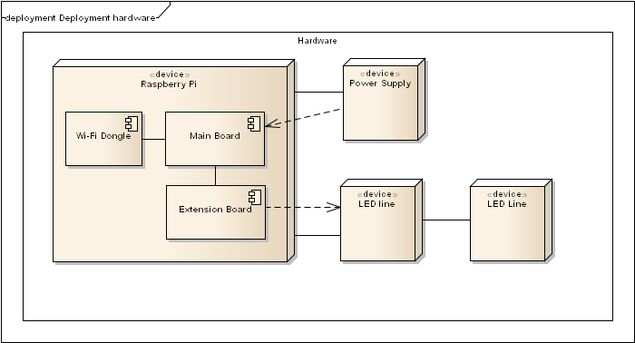
Fig. Hardware architecture
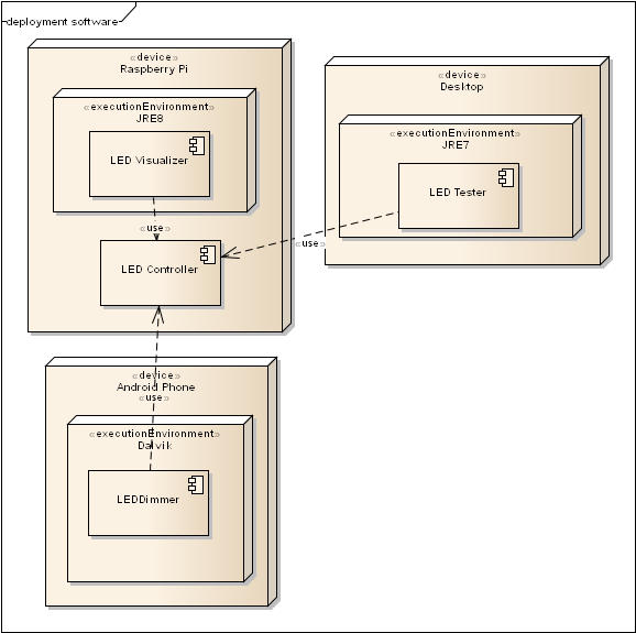
Fig. Software architecture
To create full functional system we will need:
- additional control hardware connected to Raspberry Pi and responsible for controlling the LED lights
- software controller for Raspberry Pi responsible for LED control and connection socket for remote control of the device
- test software to verify and check the hardware design
- software for the remote part e.g. Android phone
Hardware
The base board is Raspberry Pi, next we have to build on the extension pads additional module responsible for: checking button state, driving the LED strips and to provide power supply not only for the LED strips, but also for the RPi itself. It will bring only one power supply to get the things running. The schematic is as follow:
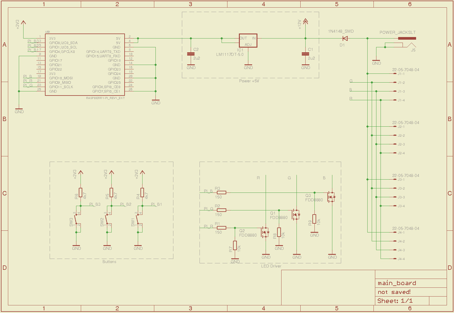
Fig. Hardware schematics
The principle is very simple. To generate any color we use one of RGB LED that with the right combination of colors will provide any color from the color palette. To do this, we cannot connect the LED strip to RaspberryPi directly, so we need a little stronger current drivers. All of these elements together are controlled by RPi with the PWM mode (so as to obtain the corresponding additivity of primary RGB colors). Additionally, to allow control of the device not only remotely from other devices we have added three buttons which are copying functionality from IKEA controller. One turns on/off the device and switches to the static color mode. The second mode is activated by second button for smooth change of color and the last button changes the mode to the switching color mode. Of course, in addition to functional elements we have placed the voltage converter from +12V (LED driver) to +5V, which comes directly into an expansion slot of RaspberryPi and this let’s RPi convert the +5V to the other power sources (e.g. +3.3V). In this way, you only need a single power supply to the device. Please remember, that we use linear power stabilizer, and RPi takes ca. 500mA of power for itself. The device should be wired with a better power sink.
Due to the fact that the Raspberry Pi does not have many hardware PWM controller output I have decided to use the software-generated PWM outputs. Accordingly with this, we currently use the GPIO0-4 output for reading of buttons and the output GPIO9-11 pins to control each color. All schematics and PCB boards are placed in the source repository. We use Eagle Schematic/PCB software for electronic layouts.
Software
Now, a brief mention of a designed software. We had to write code for many architectures and different languages. For the Raspberry Pi we have chosen the Qt libary, which gives us a solid event driven framework and a simple TCP server layer. To communicate with the remote controllers we are using the protobuf objects communication layer. The data is exchanged through the TCP link with any remote device and it provides us a way to control the main controller and to read the current settings.
Controller Software
The controller has a simplified structure. It uses the QTcp* classes and is connected by TCP to the clients. The dispatcher controller decodes the protobuf packages, and depending on the type of the Message/Command respectively perform the desired operations. In a separate thread we have running PWM controller that depending on the mode and method for controlling implements appropriate control code. Protobuf is used as a mechanism for both data and command/status retreival.
The application uses the library WiringPi and GPIO helper program to set the appropriate parameters of inputs/outputs. Application due direct access to hardware resources requires that it has to be run with root privileges. When you turn on the application it goes into the interactive console and to close the application, you can use the text “exit” and next ENTER. By default, the application listens on port 8888 for remote control. The repository has additional scripts that allows the application to run as a daemon.
Java Swing Tester
For testing purposes the test program has been developed in Java and is using the Swing library. It allows you to easily communicate the Raspberry Pi and fully control the main controller software.
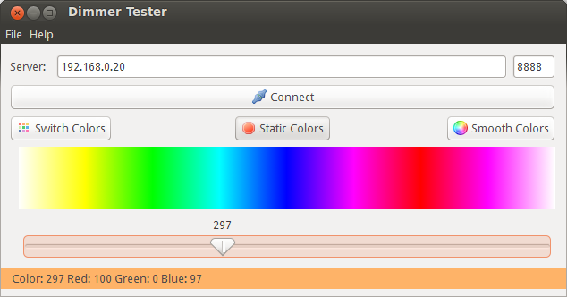
Fig. Testing application screenshot
Remote control for Android
For the purpose of remote control the application for Android OS was written. It is used to communicate with the main controller and to execute commands that are available locally in the original DIODER device. For the easy control the additional visual component was designed – the Jog dial, which easily allows you to change the color by turning the knob.
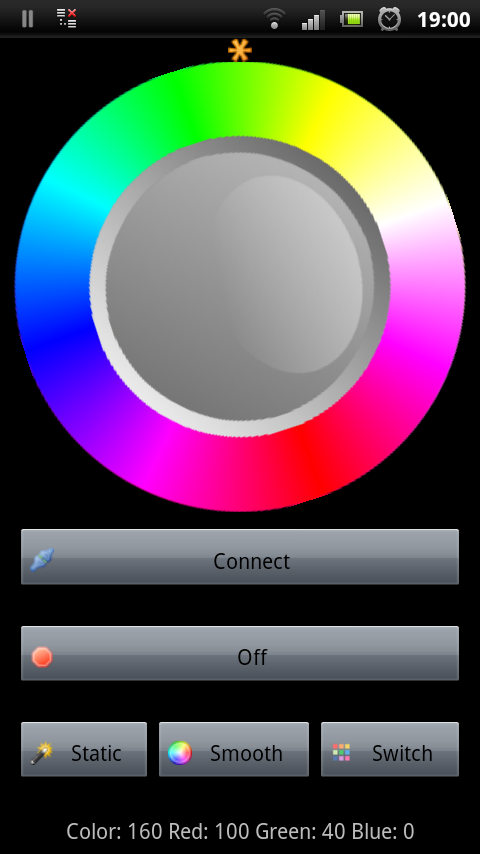
Fig. Mobile application screenshot
Rasbperry Pi
Now some information about the RaspberryPi. How to configure it, how to install needed software and how to prepare for a software development.
Operating System – we use reference Rasbian OS directly from the Raspberry Pi home page: Raspbian
Qt4/5 – we use Qt5 for the development of this project, but it can be run easily with the 4.x Qt library. Details of building and preparing to cross-compile the whole development environment (QtDevelop, Qt Core, Qt cross-compilation) is described in the section regaring Building. If there will be need for a simple guide how to create Qt5 development environment, please leave a message.
JRE8 + JavaFX – JRE8 is still available in the ‘early preview’ version but already it is worth to use. How to prepare RPi for JavaFX is described in the Building section.
WiringPi + Tools – we use version from the HEAD repository of WiringPi. Please note that the program gpio has to be in the path, since the wiringpi library uses the configuration program for I/O configuration and initialization of interrupt events (e.g. pressing the button).
Result
Licences
License for code and diagrams / layouts GNU GPLv3
License for the article and pictures CC BY-SA 3.0 Attribution-Share Alike
Source code/schematics/PCB layout
Repository URL – Bitbucket:
Repository layout
- Schematics/PCB Boards – /hardware
- Qt Pi Controller – /controller
- Android remote controller – /mobile
- UML Model – /data
Build Source Code
The master controller Qt libraries – Qt 4.x use Debian deb packages or install Qt5 using information available at Rpi Beginners Guide and using the script mentioned on this page bakeqtpi
JavaFX application, Android, Swing – using NetBeans 7.x or other environment to build java applications (ant scripts)
Installing JavaFX on Rpi – with an official guide from Oracle: JavaFX8 for ARM